Channel Bank Wiring Diagram
Schematics of the setup (a) and the working channel (b). (color online) schematic describing the channel arrangement used to Capacitor bank diagram factor phase power connection three connect
(Color online) Schematic describing the channel arrangement used to
Wiring single channel unit 2006 diagrams Different types of isolation: channel-to-channel, bank (channel-to-bus Mini channel bank
Channel bank isolation bus schematic types different earth ni supply ground figure electric
Combined turbines 12vChannel strip toolkit block diagram internal routing Bank channel t1 traditionalWiring parameters casing manufactured caping.
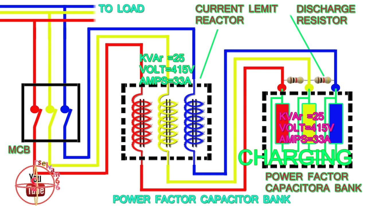
Power factor capacitor bank connection diagram,how to connect threeChannel isolation earth bank ni crosstalk noise between bus ground schematic signal types different channels figure environment electric 5 of the best amps for highs and midsIsolation channel ground earth ni understanding trusting specifications figure schematic voltage.
![Channel Strip ToolKit Block Diagram internal Routing](https://i2.wp.com/www.adt-audio.com/ProAudio/ChannelStrip/BlockDiagrams/ToolkitProcessingBsh1024.gif)
Patent us20030028874
Battery bank wiringWiring channel manufacturers, suppliers & exporters Block diagram for channel 1. (adapted from a diagram in [2])Different types of isolation: channel-to-channel, bank (channel-to-bus.
Amps mids highsChannel wiring single 2005 unit diagrams Channel strip block diagram routing toolkit internal system sitemapWiring diagrams.
![Mini Channel Bank - Connect Serial, Analog or Dry Contact, C37.94, and](https://i2.wp.com/www.tccomm.com/Content/images/FiberOpticProducts/mini-Channel-Bank-demo-diagram.jpg)
Different types of isolation: channel-to-channel, bank (channel-to-bus
Wiring diagramsChannel configuring banks Configuring channel banks.
.
![Different Types of Isolation: Channel-to-Channel, Bank (Channel-to-Bus](https://i2.wp.com/www.ni.com/cms/images/devzone/tut/bankIsolation_20180131142750.png)
![5 Of The Best Amps For Highs And Mids - Get The Best For Your Dollar](https://i2.wp.com/soundcertified.com/wp-content/uploads/2021/09/2-channel-vs-4-channel-amp-diagram.png)
![Wiring Diagrams | The Knock Box](https://i2.wp.com/theknockbox.com.au/wp-content/gallery/wiring-diagram/2006-single-channel-diagram.png)
![(Color online) Schematic describing the channel arrangement used to](https://i2.wp.com/www.researchgate.net/profile/Stefan-Heun/publication/266677062/figure/download/fig4/AS:613939683536935@1523386035657/Color-online-Schematic-describing-the-channel-arrangement-used-to-model-the.png)
![power factor capacitor bank connection diagram,how to connect three](https://i.ytimg.com/vi/DVJOm4IEeR8/maxresdefault.jpg)
![Schematics of the setup (a) and the working channel (b). | Download](https://i2.wp.com/www.researchgate.net/profile/Andrey-Zditovets/publication/330799991/figure/fig1/AS:802217632202778@1568274996807/Schematics-of-the-setup-a-and-the-working-channel-b.png)
![Different Types of Isolation: Channel-to-Channel, Bank (Channel-to-Bus](https://i2.wp.com/www.ni.com/cms/images/devzone/tut/chtoch.png)
![Wiring Diagrams | The Knock Box](https://i2.wp.com/theknockbox.com.au/wp-content/gallery/wiring-diagram/a5-single-loom.jpg)
![Patent US20030028874 - Channel set system and switching device - Google](https://i2.wp.com/patentimages.storage.googleapis.com/US20030028874A1/US20030028874A1-20030206-D00005.png)