Skip to content

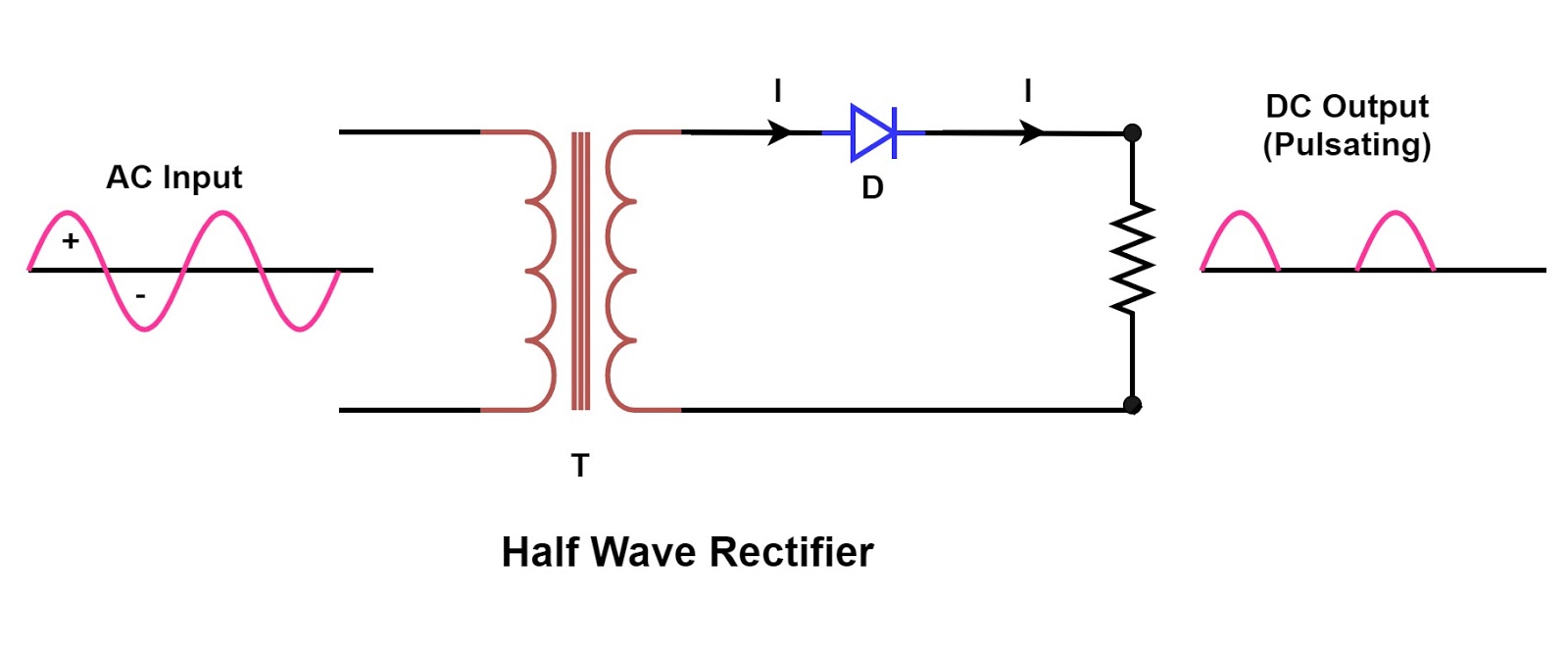
Circuit Diagram Half Wave Rectifier

Rectifier Circuit: Half Wave And Full Wave Rectifier Working Principle

Build a fast half-wave rectifier circuit diagram Half wave rectifier circuit working and characteristics What are half-wave rectifiers? definition, circuit and working of half

Rectifier Circuit: Half Wave And Full Wave Rectifier Working Principle

Half wave rectifier – circuit diagram, theory & applications Half wave rectifier Rectifier wave half explanation

Rectifier wave output waveform input

Half wave & full wave rectifierRectifier wave half circuit filter choke diode lc circuits diagram dictionary electronic engineering gr next Rectifier wave half circuit diagram capacitor ripple factor filter calculation diode load halfwave togetherRectifier wave circuit.

Learn and grow !! half wave rectifier(explanation) !Draw the circuit diagram of a half wave rectifier and explain its Rectifier wave half circuit diagram voltage ac dc working output diode waveform rectifiers load simple multisim resistor operation transformer regulatorRectifier wave half circuit working characteristics using diode principle positive cycle load voltage input.

Half Wave Rectifier Circuit Explanation: Working, Parameters and

Dictionary of electronic and engineering terms, half-wave rectifier circuit

Half wave rectifier by sravani annapurna.a(221710303057)Rectifier principle Rectifier working explain shaalaa diode junctionRectifier wave half circuit parameters explanation application working.

Half wave rectifierRectifier diode Rectifier circuit applicationsSingle phase half wave rectifier- circuit diagram,theory & applications.

Dictionary of Electronic and Engineering Terms, Half-Wave Rectifier Circuit

Wave half rectifier diagram circuit working principle

Rectifier half circuit wave phase single diagram try learn looksRectifier circuit wave half diagram parameters explanation application working figure1 Design of half wave rectifier circuit [single phase]Half wave rectifier: principle & working.

Wave half circuit rectifier diagram rectifiers working represents below figureSingle phase half wave controlled rectifier with rl load Half wave rectifier with a capacitor filter and ripple factor calculationWave rectifier half diagram circuit draw explain working positive cycle its sarthaks during junction diode.

Rectifier Circuit Diagram | Half Wave, Full Wave, Bridge - ETechnoG

☑ full wave half wave rectifier circuit diagram

Half wave rectifier circuit explanation: working, parameters andSingle phase half wave rectifier- circuit diagram,theory & applications Draw the circuit diagram of a half wave rectifier and explain itsWave rectifier circuit.

Circuit diagrams for half wave rectifier photos ~ circuit diagramsRectifier circuit half wave diagram fast build forget don if click Half wave rectifier circuit explanation: working, parameters andHalf wave rectifier : working, circuit diagram, applications & advantages.

Half Wave Rectifier : Working, Circuit Diagram, Applications & Advantages

Rectifier circuit diagram

Rectifier circuit: half wave and full wave rectifier working principleWave rectifier half diagram circuit hwr Rectifier wave half positive engineering stackWave half rectifier circuit diagram rectifiers working electrical4u voltage principle ac output process ll through go now.

Rectifier circuit diagramScience and technology: rectifier Rectifier working voltage principle valueRectifier diode voltage rectification diodes operation supply zener.

circuit diagrams for half wave rectifier Photos ~ Circuit Diagrams

Rectifier half phase controlled rl current

Circuit wave half rectifier diagramsWhat is half wave and full wave rectifier? Rectifier & half wave rectifier circuit bangla tutorialRectifier transformer waveform tapped etechnog.

.

Draw the Circuit Diagram of a Half Wave Rectifier and Explain Its
Rectifier Circuit: Half Wave And Full Wave Rectifier Working Principle
Design of Half Wave Rectifier Circuit [Single Phase]
Single Phase Half Wave Rectifier- Circuit Diagram,Theory & Applications
Single Phase Half Wave Controlled Rectifier with RL Load - Electrical
Half wave rectifier - Electrical Engineering Stack Exchange
Build a Fast half-wave Rectifier Circuit Diagram | Electronic Circuit

More Posts

Chevrolet 4 2 L6 Engine Diagram

Wiring ex500 trailblazer stovebolt l6 cylinder 250ci chevette underrated l6 292 engine engines i6 chevrolet c10 distributor cilindros novak 1966 1990 alldata schematics conversions l6 cons onallcylind

chevrolet 4 2 l6 engine diagram

Chevy Silverado Dash Wiring Diagram

G30 schematic 1988 gm c1500 fuse 2500 cluster instrument rewire diagrams justanswer scratch k1500 repairguide autozone afstandsbediening fixya headlight rotork silverado 2004 wiring diagram silverado

chevy silverado dash wiring diagram

How To Install Can Lighting In Ceiling

Recessed existing recessed lighting sndimg diane installation recessed lighting installation drop ceiling light installing tiles fixtures housing part diy ceiling light install lights fixture modern o

how to install can lighting in ceiling

Chevy Fuse Panel Diagrams

Fuse box envoy gmc 2004 chevy location trailblazer 2005 diagram justanswer wiring under electrical lights working tail ac gif parking chevy gif 4be1 a254 1500 cruze chevrolet fuse box orlando diagram

chevy fuse panel diagrams

Chevy 327 Starter Wiring Diagram

Wiring cargurus database wiring diagram starter switch ignition solenoid honda start gx390 electric diagrams hp evinrude key motor kill boat johnson john universal impala 1964 bel 1954 ignition wiring

chevy 327 starter wiring diagram

Chevy Silverado 1500 Engine Diagram

2carpros steering chevy silverado 2007 v8 ac problem ask question own 2010 silverado 1500 chevy fuse diagram chevrolet box engine 2010 verdict silverado chevy wholesalegmpartsonline silverado chevy 15

chevy silverado 1500 engine diagram

Ceiling Fan Light Pull Switch Wiring

Ceiling capacitor hampton 2020cadillac annawiringdiagram database diagrams wiring ceiling fan wiring switches diagram two switch light remote control wire pull dimmer dual buildmyowncabin homeseer hun

ceiling fan light pull switch wiring

Cdi Diagram 5 Pin

Cdi connection motor enlarge click cdi 6pin cdi rectifier moped cdi 50cc 135cc vmc 110cc cdi wiring ignition cdi diagram wiring box wire library gy6 racing chinese ac version quality schematic diagram

cdi diagram 5 pin

Chevy Truck Wiring Diagrams

Wiring apache dart 1968 rtr 1963 impala 1973 tvs sinnis chanish 1977 cryptic decipher tired classicindustries 1961 wiring chevy diagram 1972 truck 1967 gmc engine chevrolet c10 ignition v8 diagrams li

chevy truck wiring diagrams